Current Process Parameters (Spring 2020)
Processing Equipment
 CMOS Oxidation Furnace
 Other Equipment for Oxidation
Process Procedure
In the manufacturing of integrated circuits, field oxide is used to isolate the devices from one other. In our CMOS process, the field oxide is also used to define the source and drain regions for subsequent diffusions. Gate oxidation is much thinner and composed of better-quality oxide than the field oxide. The presence of the gate oxide under a metal layer and above the substrate creates the MOS (metal-oxide-semiconductor) structure. To achieve high-quality oxide growth (i.e. a uniform film with good dielectric properties), “DRY” oxidation alone is employed when gate oxide is grown. The process is slower than “WET” oxidation. On the other hand, wet oxidation is used to grow field oxide since the quality of the dielectric properties of the field oxide are not as critical as they are for the gate oxide. Also, the field oxide is much thicker than the gate oxide, and the rate of wet oxide growth is faster than that of dry oxidation.
During this procedure, a layer of silicon dioxide is grown on a wafer surface by thermally oxidizing the silicon substrate. The oxidation process consists of the following steps:
- FURNACE PREPARATION
- LOADING WAFERS INTO FURNACE
- FIELD OXIDATION
- GATE OXIDATION
- UNLOADING WAFERS
- OXIDE THICKNESS MEASUREMENT
- WAFER STORAGE
1. FURNACE PREPARATION
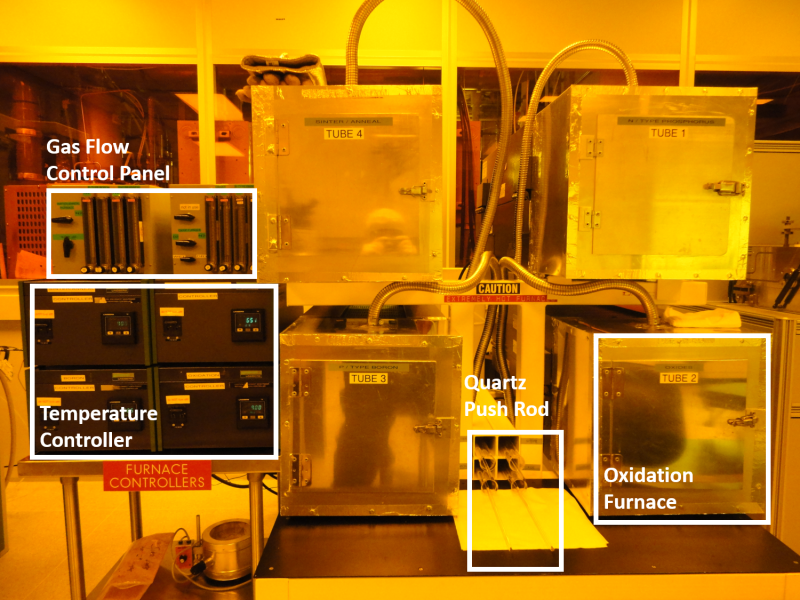
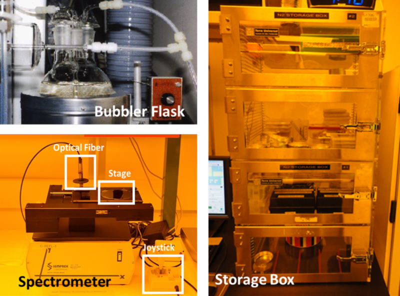
An RCA Clean of wafers should be performed immediately prior to any oxidation process. During the RCA Clean, the oxidation furnace should be set-up. The Gas Flow Control Panel controls gas flow to all four furnaces – Oxidation, Phosphorus diffusion, Boron diffusion, and Anneal furnaces. First, verify that the Gas Flow Control Panel is set in the N2 position. Nitrogen is flowing into the furnaces in order to keep them clean and dry. Next, turn on the oxidation furnace by adjusting the Oxidation Furnace Temperature Controller to 900 °C. Then, fill the Bubbler Flask behind the furnace with deionized water up to the marked line and turn the controller knob to “8.” This will start heating the water in the Bubbler Flask to a temperature between 90 and 100 °C. Heating of the Bubbler Flask is necessary only for the wet oxidation process.
2. LOADING WAFERS INTO FURNACE
At the completion of the RCA Clean, remove the Quartz Boat from the Oxidation Furnace using the designated Quartz Push Rod and the Quartz Boat Loader. Keep in mind to wear high temperature gloves when handling quartz-ware since the furnace temperature is 900 °C. DO NOT hold the Push Rod above the white mark. Keep the boat in the Boat Loader, and carefully set the Boat Loader down on two parallel quartz rods on the table between furnace tubes, letting the boat cool down. Again, NEVER touch the rod with hands above the white mark to avoid introducing contamination into the furnace.
Now, load the RCA-cleaned wafers into the boat. Using Teflon or Teflon-coated tweezers, carefully load the wafers onto the Quartz Boat aligned with slits. Avoid passing your arms or head over the cleaned wafers and the boat. Remove the Quartz End Cap from the entrance of the oxidation tube and return the wafers on the boat to the oxidation furnace with the Boat Loader. In order to prevent thermal stress which could cause the wafers to fracture, allow the wafers to sit just inside the mouth of the open furnace for two minutes. Very slowly push the rod to the point where the white mark on the rod is flush with the metal furnace door. This indicates that the center of the Quartz Boat is at the center of the furnace tube. The pushing speed would be approximately 1 ft/minute. Now place the Quartz End Cap on the end of the Quartz Oxidation tube loosely. Shut the metal door.
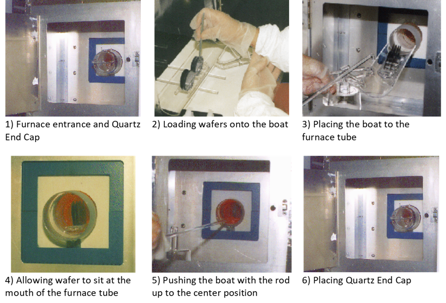 Wafe Loading Sequence
3. FIELD OXIDATION (Wet oxidation)
The Oxidation Furnace needs to be heated to the temperature at which the field oxidation will be performed. In our example, the temperature of the field oxidation is 1100 °C, so the Temperature Controller is set to ramp up to this temperature. The reason we are raising the temperature slowly is to avoid thermally stressing and perhaps fracturing the wafers. The process sequence is:
Wafer Load in N2 ⇒ Dry O2 5 min ⇒ Wet O2 15 min ⇒ Dry O2 5 min ⇒ Wafer Unload in N2
Wait until the temperature is stabilized for about 10 minutes. Set the Gas Flow Control Panel to the “Dry” configuration to begin dry oxidation, then turn the Gas Flow Control valve to O2. In this configuration, dry oxygen is flowing into the oxidation furnace. Check the flow meter and adjust the flow rate to 2000 sccm.
When five minutes have elapsed, it is time to switch to wet oxidation. As a safety precaution, first remove the cap from the Bubbler Flask. Now set the Gas Flow Control Panel to the “Wet” configuration. In this configuration, oxygen is being bubbled up through the deionized water in the Bubbler Flask, generating a combination of oxygen and steam which is fed into the oxidation furnace.
When fifteen minutes have elapsed, switch back to dry oxidation by setting the Gas Flow Control Panel to the “Dry” configuration. Turn OFF the HEATER of the Bubbler Flask.
When five minutes have elapsed, start nitrogen flow through the tube, i.e., return the gas valve to the N2 configuration. Set the Temperature Controller to ramp down to 900 °C, locking in ramp mode and wait 10 minutes for it to cool to approximately 900 °C.
4. GATE OXIDATION (Dry oxidation)
The Gate oxidation will thermally oxidize the silicon substrate with oxygen only, growing a thin gate oxide, approximately 40 nm. The oxidation furnace needs to be heated to the temperature at which the gate oxidation will be performed. In this example, the gate oxidation is to be performed at 1000 °C, so the Temperature Controller is set to ramp up to this temperature. The furnace will heat at 10 °C/minute; thus, it will take about 10 minutes for the furnace to go from 900 °C to 1000 °C. The process sequence is:
Wafer Load in N2 ⇒ Dry O2 40 min ⇒ Wafer Unload in N2
Once the oxidation temperature has been reached, set the Gas Flow Control Panel to the “Dry” configuration, flowing dry oxygen into the furnace. Check the Flow Meter to 2000 sccm. When forty minutes have elapsed, turn the oxidation furnace valve to N2. Finally, set the furnace Temperature Controller to ramp down to 900 °C. Once again this will take about 10 minutes. Note that during the Gate Oxidation the heater of the Bubbler Flask should remain OFF throughout the process.
5. UNLOADING WAFERS
The oxidation process has been completed and the furnace temperature remains at 900 °C with N2 flow. Open the metal door and remove the Quartz Door Cap while wearing the high temperature gloves on. Using the Quartz Push Rod, carefully pull the Quartz Wafer Boat to the front of the furnace very slowly. Again, let the wafers sit for a couple of minutes in the furnace entrance. Then move the Quartz Wafer Boat using the Quartz Boat Loader, and carefully set the Boat Loader down on two parallel quartz rods on the table between furnace tubes. Allow the wafers to cool down completely in the boat before placing them back into the black box. With the Quartz Boat Loader, return the empty Quartz Boat to the oxidation furnace. Slowly push the boat into the furnace with the Quartz Push Rod up to approximately quarter of the way into the furnace. Loosely replace the Quartz End Cap and store the Boat Holder inside the metal door.
6. OXIDE THICKNESS MEASUREMENT
Once the wafers have been cooled, the thickness of the oxide layer can be measured using an ellipsometer or a spectrometer. First, place a wafer on the chuck and the stage is adjusted so that the beam is reflected from the polarizer toward the analyzer for an accurate reading. Then press a measuring button from the software. Record data in a cleanroom notebook.
7. WAFER STORAGE
Upon completion of the oxidation process, the cooled wafers should be stored in the Dry Box Storage Area. The Dry Box Storage is an enclosed cabinet which has nitrogen gas circulating through it. The circulating gas prevents dust from settling on the wafer surface during storage.
(Back to top)