Current Process Parameters (Spring 2020)
Processing Equipment
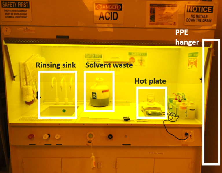 General Purpose Fume Hood
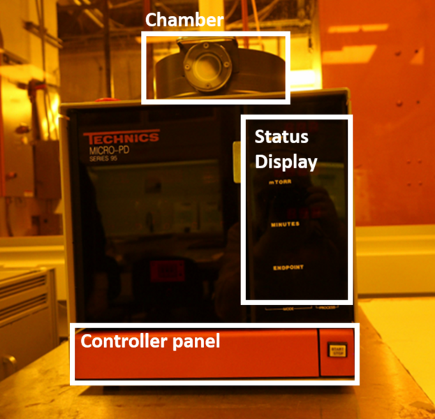 Technic Micro-PD RIE
Process Procedure
The etching process is used in microfabrication to chemically remove selected layers from the surface of a wafer during manufacturing. For many etch steps, part of the wafer is protected from the etchant by a masking material which resists the etching process and protects the underlying materials. A common masking material is photoresist which has been patterned using photolithography. Two fundamental types of etchants are liquid-phase (wet) and plasma-phase (dry). The etching process is generally used for: 1) removal of remaining contaminants on the wafer surface from previous processes; 2) removal of unnecessary area of dielectric material from the wafer surface by masking necessary area; 3) removal of unnecessary metal layer for making contacts between devices; and 4) removal of photoresist or other masking materials from the previous etching process.
In this procedure, oxide etch, metal etch, and plasma clean processes are described as examples.
- FIELD OXIDE ETCH (WET)
- METAL ETCH (WET)
- PLASMA CLEAN (DRY)
1. FIELD OXIDE ETCH (WET)
A field oxide layer on a wafer is etched using a buffered oxide etchant (BOE). The pre-mixed etching solution is provided by the IEN cleanroom. For chemical safety, personal protective equipment (PPE) should be worn throughout the oxide etching procedure.
First, pour the solution in a polypropylene beaker up to a 400 or 500 ml line, which is enough amount to dip a wafer in a holder into the solution. Using Teflon tweezers, carefully place the wafer into a Teflon wafer holder and lock it up with a slider. Load a wafer in a single wafer carrier. Set a timer, then immerse the wafer in the BOE solution for a given time. Usually, it takes 6 to 8 minutes to dissolve a 300- to 500nm thick field oxide layer. Then, immediately immerse the wafer into the other beaker under running D.I. water and rinse it for at least two minutes. Move the wafer holder with the wafer to the drying station and blow the wafer and the holder using the N2 blowers. After the wafer is dried, inspect the wafer with a microscope to check for any imperfections in the pattern etch. The oxide wet etching is isotropic, which causes undercut below a masking material such as photoresist. If there are residuals of the oxide layer in the patterns, repeat the etching step with a reduced etching time.
2. METAL ETCH (WET)
An aluminum layer is etched using a metal etching solution. The etching solution consists of Phosphoric acid (H3PO4), Nitric acid (HNO3), Acetic acid (CH3COOH) and water (H2O). The ingredients are mixed by the volumetric ratio of 16:1:1:2 respectively. The solution is poured in a quartz container and heated up to the temperature range between 40 - 50 °C on a hot plate. In order to keep the temperature uniform, place a magnetic stirring bar in the container and rotate it at the rate of 100 - 200 rpm. A thermometer is then placed in the solution to precisely monitor the temperature. For chemical safety, personal protection equipment (PPE) should be worn throughout the metal etching procedure.
Once the temperature of the solution has stabilized, load a wafer in a single wafer basket and immerse the wafer in the solution. During the etching step, bubbles will be generated as a result of chemical reaction at the surface of the aluminum layer. After you no longer can see the aluminum layer on the wafer surface and the assigned time passed, move the wafer to a rinsing beaker and rinse it at least 3 minutes with D.I. water. Then, blow the wafer dry with a nitrogen gun.
After the wafer is dried, inspect the wafer with a microscope to check for any imperfections in the pattern etch. Typically, the bubbles tend to stick on the wafer surface and prevent the metal layer from being etched, which causes a metal residual left between small-size patterns. This can cause shortages of metal lines. If there are many shorted patterns, repeat the etching step with a reduced etching time.
The acid mixture can be drained in the fume hood sink with flowing water after it is fully cooled down. Flush water down the drain for at least three minutes after poring the solution out. Other lab materials such as the thermometer, magnetic stirring bar and containers should also be rinsed in D.I. water and dried.
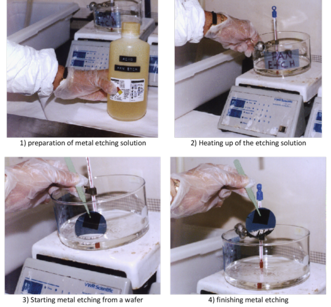 Metal etching sequence
3. PLASMA CLEAN (DRY)
A plasma clean process removes residual organics and thin oxides from the surface of a sample. Typically, wafers with metal layers are processed because cleaning solutions can damage the metal layers. Oxygen plasma is used for the plasma clean process for removing organic (carbon) residuals. All removed contaminants are pumped out of the chamber by the vacuum system. In the Instructional Cleanroom, a Technics Micro-PD RIE is used for the plasma clean.
First, turn on VENT
switch in the control panel and wait for 10 seconds until hearing a hissing sound from the chamber. Turn off the VENT
switch. Open the processing chamber and place wafers on the bottom plate. The plate size is 6-inch in diameter so up to seven 2-inch wafers can be loaded. Carefully close the chamber lid and turn on VACUUM
switch.
Once the chamber pressure reaches below 55 mTorr, turn on AUTOMATIC,
RF,
and GAS1
switches sequentially. Then Press START/STOP
button on the right side of the controller panel. Oxygen flow rate is approximately 13 sccm and chamber pressure is set to 150 mTorr. Once the RF power is supplied at 100 W, the timer will count 12 minutes. Check the chamber window in a light blue color.
After the time has elapsed, the RIE will sound beeps. Push the START/STOP
button to finish the process and turn off RF
and GAS1
switches. Toggle the AUTOMATIC
switch to MANUAL.
After waiting for a minute to evacuate the chamber, turn on VENT
switch to open the chamber. Open the processing chamber and unload the processed wafers. Then, carefully close the chamber lid and turn on VACUUM
switch to keep the chamber pumped down.
(Back to top)