Current Process Parameters (Spring 2020)
Processing Equipment
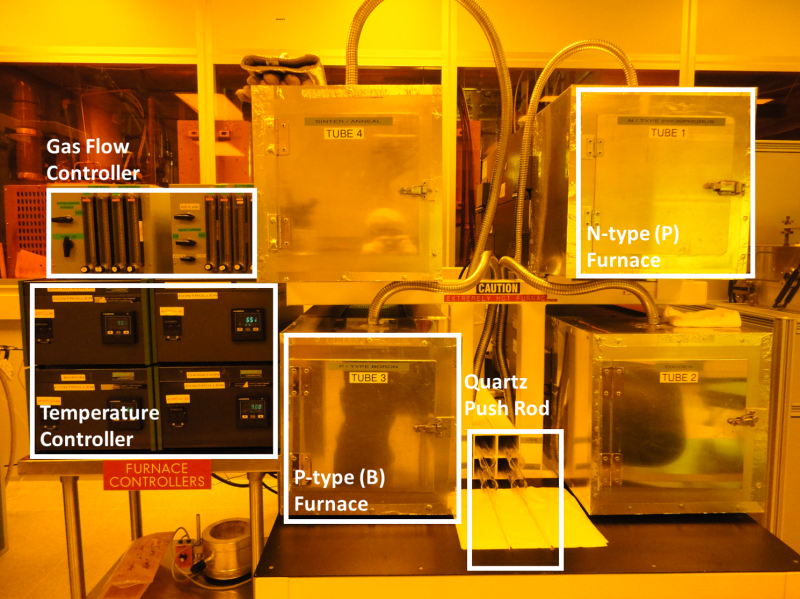 CMOS Diffusion Furnace
Process Procedure
Diffusion can be defined as the movement of particles from regions of high concentration to regions of lower concentration. In integrated circuit fabrication, diffusion is used to introduce dopants in controlled amounts into the semiconductor substrate. In our CMOS process, diffusion is used to form: 1) the sources and drains in MOS transistors, 2) integrated resistors, and 3) doped wells in CMOS fabrication.
P-type Diffusion: The solid source diffusion process with Boron will dope P-well regions and source and drain regions of PMOS transistors. The boron source (BoronPlus GS-126) is a planar diffusion source, exhibiting the unique diffusion-controlled evolution rate of B2O3 during use. The source is produced from a glass containing B2>O3 and the extremely stable oxides of BaO, MgO, Al2O3 and SiO2. Typically, the source in a high temperature furnace deposits a glassy film of B2O3 on the silicon wafer surface, and this thin layer of B2O3 provides the elemental boron for the diffusion into the silicon wafer with the reaction:
2 B2O3 + 3 Si → 4 B + 3 SiO2
This is an infinite-source diffusion or pre-deposition. After the desired amount of boron is dissolved into the silicon wafer, the glassy film is removed, and then the boron atoms are diffused deeper into the silicon wafer during another high temperature step called a limited-source diffusion or drive-in.
N-type Diffusion: The solid source diffusion with Phosphorus will dope N-well regions and the source and drain regions of NMOS transistors. The phosphorus source (PhosPlus TP-250) is a planar diffusion source, exhibiting the unique diffusion-controlled evolution rate of P2O5 during use. The source contains P2O5 and the extremely stable oxides of Ta2O5, Al2O3 and/or La2O3. The P2O5 is combined with Al2O3 or La2O3 and it only evolves when the sources are heated to the specified doping temperatures. The thin layer of P2O5 provides the elemental phosphorus for the diffusion into the silicon wafer with the reaction:
2 P2O5 + 5 Si → 4 P + 5 SiO2
This is an infinite-source diffusion or pre-deposition. After the desired amount of phosphorus is dissolved into the silicon wafer, the glassy film is removed, and then the phosphorus atoms are diffused deeper into the silicon wafer during another high temperature step called limited-source diffusion or drive-in.
The diffusion process consists of the following steps:
- SOURCE PREPARATION
- LOADING WAFERS AND SOURCES INTO FURNACE
- PRE-DEPOSITION OF BORON
- PRE-DEPOSITION OF PHOSPHORUS
- UNLOADING WAFERS
- SHEET RESISTANCE MEASUREMENT
- WAFER STORAGE
1. SOURCE PREPARATION
Before using the sources for the first time, it is necessary to clean them. The cleaning procedures of different sources are described in the following table:
The sources require an aging time at the intended deposition temperature to be sure all moisture has been removed and to achieve a constant evolution rate of B2O3 or P2O5. The recommended minimum aging time is from a few hours from high temperature processes to as long as 24 hours for low temperature processes. Since the thin film of B2O3 or P2O5 will be deposited onto the other sources during the aging process, RCA-cleaned silicon wafers are used as spacers between the sources. The spacer wafers should always remain next to the source wafers.
Once the sources are cleaned and aged, it is highly recommended to store the sources in the diffusion Quartz Boats at an elevated temperature, such as 650 °C, in dry nitrogen. If the sources are properly stored, they can be available to use for future processes without extra cleaning or aging steps.
2. LOADING WAFERS AND SOURCES INTO FURNACE
An RCA Clean of wafers should be performed immediately prior to any diffusion process. During the RCA Clean, the Diffusion Furnace of P-type or N-type should be set. Verify that the Diffusion Furnace temperature is set to 650 °C and the Gas Flow Control Panel is set in the N2 position. Nitrogen is flowing into the furnaces in order to keep them clean and dry. At the completion of the RCA Clean, load the silicon wafers into the boat with sources.
First, open the metal furnace door and remove the Quartz Door Cap while wearing high temperature gloves on. Using the Quartz Push Rod, carefully pull the Quartz Wafer Boat containing the boron or phosphorus sources and spacer wafers to the front of the furnace very slowly. Let the sources and wafers sit for a couple of minutes in the furnace entrance, and then remove the Quartz Wafer Boat using the Quartz Boat Loader. Carefully set the Boat Loader down on two parallel quartz rods on the table between furnace tubes.
Using Teflon or Teflon-coated tweezers, carefully move the spacer wafers to the empty slots of the Boat and load the wafers into the slots. The wafers should be inserted such that the device side of each is facing a source wafer. There are two wafer slots between sources, allowing for a device wafer facing both sides. Avoid passing your arms or head over cleaned wafers.
The Diffusion Furnace needs to be heated up to the temperature at which the pre-deposition will be performed. For example, turn the Furnace Temperature Controller up to the temperature of 890 °C for P-well pre-deposition process with boron sources; 935 °C for P+ source/drain pre-deposition process with boron sources; or 950 °C for N+ source/drain pre-deposition with phosphorus sources.
With the Quartz Boat Loader, return the wafer-loaded Quartz Boat to the furnace. Slowly push the boat into the mouth of the furnace with the Quartz Push Rod, allow to sit for a couple of minutes in the furnace entrance, and then push the Boat into the center of the tube using a continuous movement until you reach the center zone. The center zone is reached when the white mark of the rod is flush with the metal furnace door. NEVER touch the rod with hands above the white mark to avoid introducing contamination into the furnace. Loosely return the Quartz Door Cap to the entrance of the furnace.
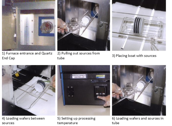 Wafe Loading Sequence
3. PRE-DEPOSITION OF BORON
Wait until the temperature has stabilized about 10 - 15 minutes, then start a timer for the pre-deposition process. For example, turn the Furnace Temperature Controller up to the temperature of 890 °C for the P-well pre-deposition process or 935 °C for the P+ source/drain pre-deposition process. Nitrogen has been flowing throughout the process at the rate of 2000 sccm.
When the pre-deposition time has elapsed, the boron pre-deposition is completed. The processing time is 14 minutes for P-well pre-deposition and 25 minutes for P+ source/drain pre-deposition. Using the Quartz Rod, pull out the Quartz Boat back to the entrance of the furnace in a slow and continuous movement manner. Finally, set the Furnace Temperature Controller to down to 650 °C, and continue to the unloading step.
4. PRE-DEPOSITION OF PHOSPHORUS
Wait until the temperature has stabilized about 10 - 15 minutes, then start a timer for the pre-deposition process. For example, turn the Furnace Temperature Controller up to the temperature of 950 °C for the N+ source/drain pre-deposition process. Nitrogen has been flowing throughout the process at the rate of 2000 sccm.
When the pre-deposition time has elapsed, the phosphorus pre-deposition is completed. The processing time is 90 minutes for the N+ source/drain pre-deposition. Using the Quartz Rod, pull out the Quartz Boat back to the entrance of the furnace in a slow and continuous movement manner. Finally, set the Furnace Temperature Controller to down to 650 °C, and continue to the unloading step.
5. UNLOADING WAFERS
Open the metal furnace door and remove the Quartz Door Cap while wearing high temperature gloves on. Using the Quartz Rod, carefully slowly pull the Quartz Wafer Boat containing the sources and the wafers to the entrance of the furnace.
Let the sources and wafers sit at the entrance of the furnace for at least five minutes. Then move the Quartz Wafer Boat using the Quartz Boat Loader and carefully set the Boat Loader down on two parallel quartz rods on the table between furnace tubes. Allow the wafers to continue to cool before unload the wafers from the Boat. Unload the processed wafers to a Teflon carrier in the black box with the tweezers and return the spacer wafers back to the slots between the sources. With the Quartz Boat Loader, return the Quartz Boat with the sources and spacer wafers to the Diffusion furnace. Slowly push the boat into the furnace with the Quartz Rod. Push the boat in the center of the tube. Loosely replace the Quartz End Cap and store the Boat Holder inside the metal door.
Verify that the Diffusion Furnace temperature is stabilized at 650 °C, and the Gas Flow Control Panel is set in the N2 position. Nitrogen is flowing into the furnaces in order to keep them clean and dry.
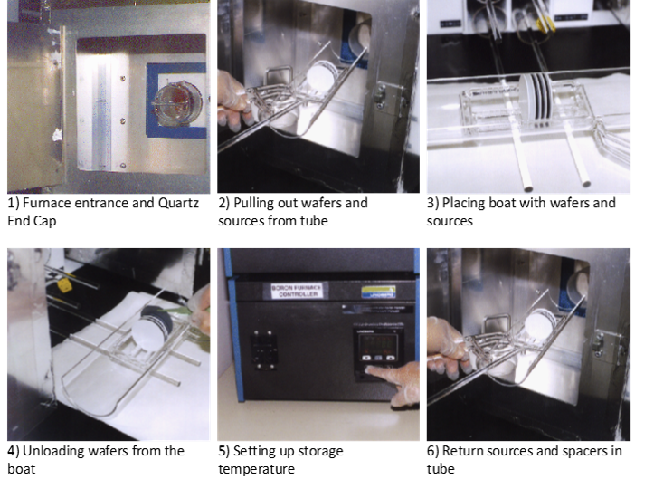 Wafe Unloading Sequence
6. SHEET RESISTANCE MEASUREMENT
The wafers are covered with a borosilicate glass (BSG) film after the P-type pre-deposition process or with a phosphosilicate glass (PSG) film after the N-type pre-deposition process. The exposed p-well region or source/drain region of silicon wafers are doped. Other areas are masked from diffusion by the field oxide layer. When the wafers are cool, place them in the Teflon carrier and dip into the HF bath of the CMOS Clean Fume Hood for two minutes, followed by a D.I. water rinse for 5 minutes and a spin dry. This is to remove the BSG or PSG layer from the surface that is no longer needed. A monitoring wafer with no patterns is taken from the carrier and brought to a Four Point Probe. Sheet resistance data is measured from multiple positions with the Four Point Probe.
7. WAFER STORAGE
Upon completion of the P-type or N-type diffusion process, the cooled wafers should be stored in the Dry Box Storage Area. The Dry Box Storage is an enclosed cabinet which has nitrogen gas circulating through it. The circulating gas prevents dust from settling on the wafer surface during storage.
(Back to top)