Device Testing Procedure
Inverters can be constructed by using two complementary transistors in a CMOS configuration. The other way is the usage of a single NMOS or PMOS transistor coupled with a resistor, but this configuration has the disadvantage of more power consumption than the CMOS configuration. The logical functionality of a binary inverter is trivial to test; if the input is at the logic high then the output should be logic low and vice versa. Also, of interest is the inverter threshold voltage (a different quantity than FET threshold voltage) and its output logic swing, to wit, the difference between output high and output low.
Four probes are needed to test a CMOS inverter. One power supply (Keithely 2430C SMU) is used to power the inverter (VDD and VSS), while the other power supply (Tenma) is used to provide input voltages. The input voltage of the inverter is varied from 0 V to 5 V, and the input and output voltages are measured with voltmeters, respectively.
Choose any inverter on a CMOS wafer, determine, and record the width and length of the NMOS and PMOS transistors which comprise the inverter. The lengths can be either 10 µm, 20 µm, or 40 µm. The width of each device is 180 µm. The functionality of the inverter may be tested with the following procedure:
- Using the Keythley 2430C, set the VDD power supply to 5 V and the VSS supply to 0 V (Ground).
- Using the Tenma power supply, sweep VIN from 0 V to 5 V in any increment. Using the digital multimeter, measure and record VOUT for each value of VIN. The high and low output levels of the inverter can be found by setting the input voltage to 0 V and then 5 V. The threshold voltage may be found by varying the input voltage until the output voltage is the average of the high and low output levels.
- Plot the voltage transfer characteristic (VTC) of the inverter (VOUT vs. VIN) using the collected data.
- Based on the VTC plot, estimate and record VOH, VOL, VIH, and VIL. Compute the noise margins of this inverter (NMH and NML).
Device Testing Setup
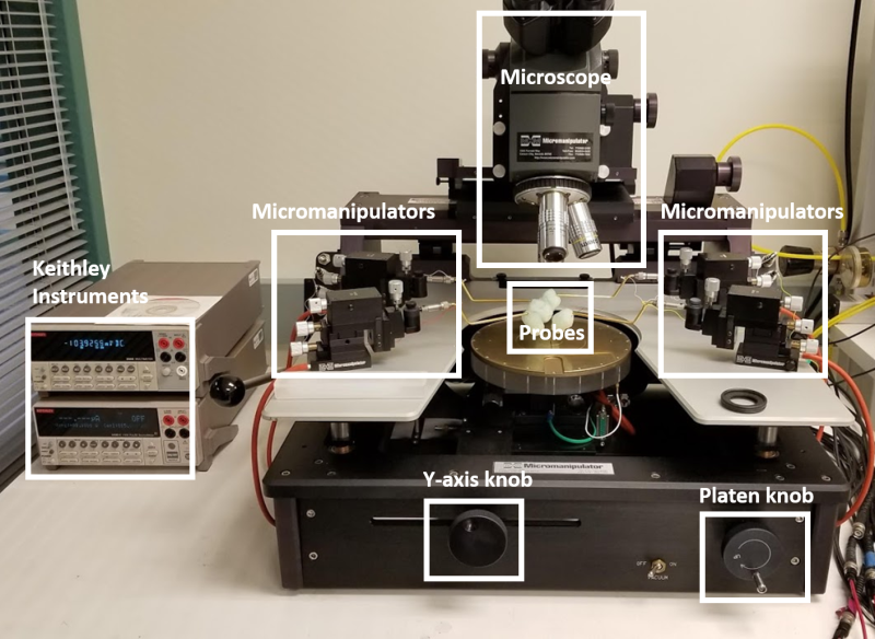 Micromanipulator Probe Station and Keithley Instruments
Examples of Testing Results
(Back to top)