Device Testing Procedure
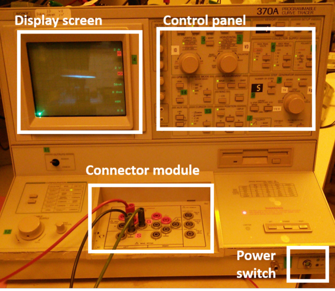
A DC characteristic curve of a diode can be measured using the curve tracer in a similar manner to that used for the MOSFETs. Since diodes are two terminal devices, nothing should be connected to the gate plug of the curve tracer. Additionally, care must be taken to connect diodes to the curve tracer with the correct polarity, otherwise no characteristic curve will be observed. The anode (p-side) of each diode is connected to the pad on the right, while the cathode (n-side) is connected to the left pad. The anode pad connects to D (C) plug, and the cathode pad to S (E) plug.
Once the diode is connected to the curve tracer, the following procedure may be used to obtain DC characteristic curves:
- Turn on the curve tracer using the switch located at the base of the machine on the front right.
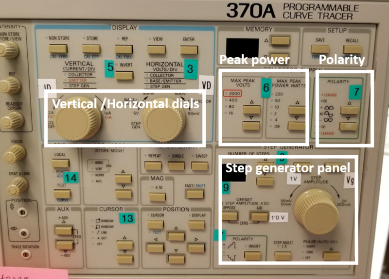
- In the Display section, adjust the horizontal units per division to 500 mV/div and the vertical units per division to about 500 µA/div.
- In the section marked Collector Supply, make sure the maximum peak voltage setting is 16 V and the maximum peak power setting is 0.08 W (these settings are the default).
- The collector supply polarity setting should be AC for diode devices.
- Set the terminal selection on the lower-right of the curve tracer to left and set the output switch on the front lower-left panel to enabled.
- Slowly increase the maximum drain sweep voltage with the Variable Collector Supply knob located on the lower-left of the machine. A DC curve should appear on the screen. Adjust the horizontal and vertical units per division knobs as necessary to view the curves.
- After obtaining the turn-on voltage from the forward biased diode, adjust the horizonal to 2 V/div and vertical 2 mA/div.
- Keep increasing the Variable Collector Supply until the breakdown current of the diode from the reverse biased region is measured.
Device Testing Setup
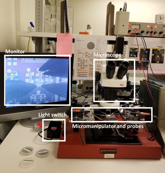
 Signatone Probe Station
 Tektronix 370A Curve Tracer
 Control Panel of the Curve Tracer
Examples of Testing Results
(Back to top)