Device Testing Procedure
A curve tracer biases a transistor under test at different points and measures resulting voltages and currents. One valuable set of DC characteristics for FETs measures the relationship between drain current ID and drain-to-source voltage VDS at various gate-to-source voltages VGS in common-source configuration (this is analogous to collector current IC versus collector-to-emitter voltage VCE at different base currents IB with a common-emitter bipolar transistor). To perform this measurement, the curve tracer sweeps VDS from zero to certain maximum voltage for each of a set of pre-defined values of VGS and measures the resulting drain current, ID. Plotting this data on a graph shows the DC characteristics of the FET in several useful biasing modes (cut-off, linear/triode, and saturation). This can be used to evaluate transistor performance and to calculate several useful figures of merit--transconductance, channel-length modulation effect, saturation, and breakdown voltage, etc.
For measurement of ID versus VDS of MOSFETs probes should be connected to the source, drain, and gate pads of the device. The probes should be connected to the left set of plugs on the Tectronix 370A Curve Tracer accordingly.
Once the transistor is connected to the curve tracer, the following procedure may be used to obtain DC characteristic curves:
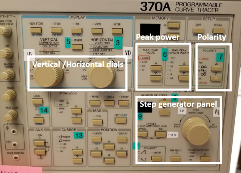
- Turn on the curve tracer using the switch located at the base of the machine on the front right.
- In the Display section, adjust the horizontal units per division to 500 mV/div and the vertical units per division to about 100 µA/div.
- If the device being tested is a pMOS transistor, turn Invert on, otherwise leave it off.
- In the section marked Collector Supply, make sure the maximum peak voltage setting is 16 V and the maximum peak power setting is 0.08 W (these settings are the default).
- The collector supply polarity setting should be positive for nMOS devices and negative for pMOS devices.
- For the “Step Generator”, Set the step polarity to positive for nMOS devices or negative for pMOS devices.
- Set the step function to voltage, the number of steps to 10, and the step amplitude to 500 mV. It supplies stepwise VGS voltages from 0 to 5 V.
- Set the terminal selection on the lower-right of the curve tracer to left and set the output switch on the front lower-left panel to enabled.
- Slowly increase the maximum drain sweep voltage with the Variable Collector Supply knob located on the lower-left of the machine. DC curves should appear on the screen. Adjust the horizontal and vertical units per division knobs as necessary to view the curves.
- Repeat steps 2-9 for both NMOS and PMOS transistors of all gate lengths (2 µm, 5 µm, 10 µm, 20 µm, and 40 µm).
Device Testing Setup
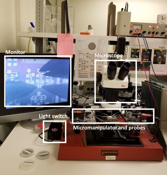 Signatone Probe Station
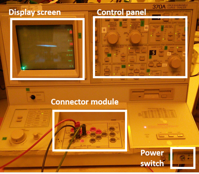 Tektronix 370A Curve Tracer
 Control Panel of the Curve Tracer
Examples of Testing Results
(Back to top)